Walkclock is a Christmas present that retraces the route my father took in 2019 walking between the 88 temples on the Shikoku island of Japan.
It uses a HUB75E-style 64x64px RGB LED matrix driven by an STM32H743, which also drives a secondary LCD display on the back for a menu. The STM32’s RTC is used to keep time, and a uBlox MAX-M8Q GPS receiver is used to obtain a precise UTC time reference and calibrate the STM32’s 32kHz oscillator.
The base map for Shikoku was commissioned from @SirLazz on Twitter, thank you!
Source code and hardware designs are available from GitHub above.
Features
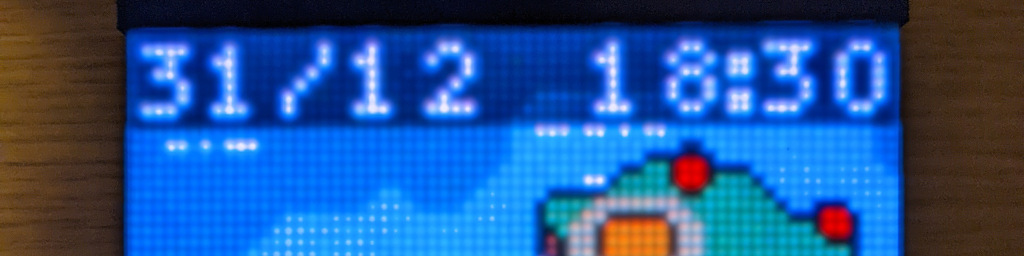
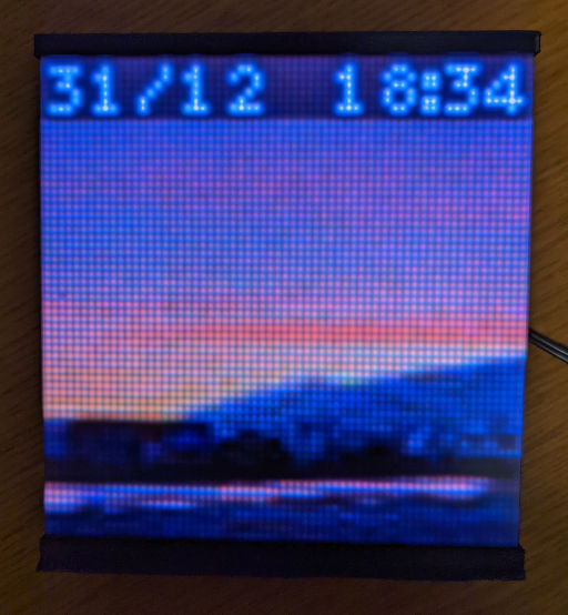
- Displays the current date and time, synchronised to GPS and maintained by battery when powered off
- Implements UK daylight savings time automatically
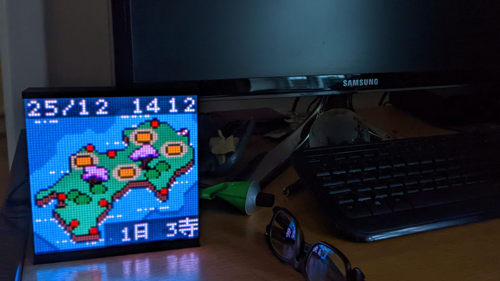
- Shows either a large clock face, or a map of Shikoku island
- Dims the display at night
- Draws a route around Shikoku which advances each day, showing all 88 temples
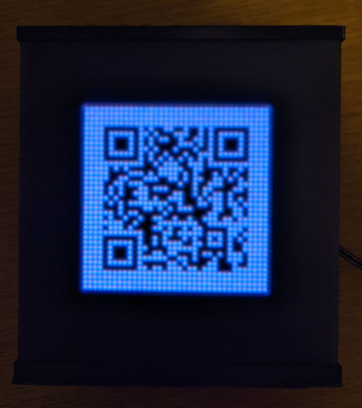
- Displays a QR code linking to the original blog post for each day of the walk
- Displays a photograph from each day, at the top of the hour or on demand
- Clock interface can be run on a desktop in the simulator
Route Animation
You can see a video recording from the simulator showing the animation of the entire route around the 88 temples:
Menu System
The menu system is used to change settings, which are stored in the battery-backed RTC memory to persist them between power cycles. The menu interface is shown in this video from the simulator:
Hardware
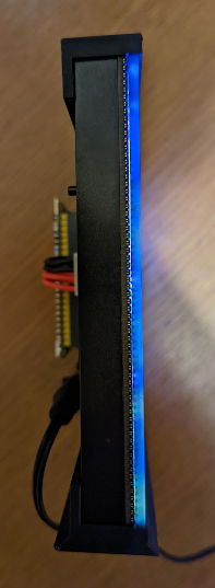
The clock consists of a HUB75E 64x64 LED panel which is sandwiched between a top and bottom 3d printed housing. A laser-cut panel of dark acrylic acts as a diffuser for the LEDs and is also held in place by the 3d printed housing. The control electronics plug directly into the LED panel on the back.
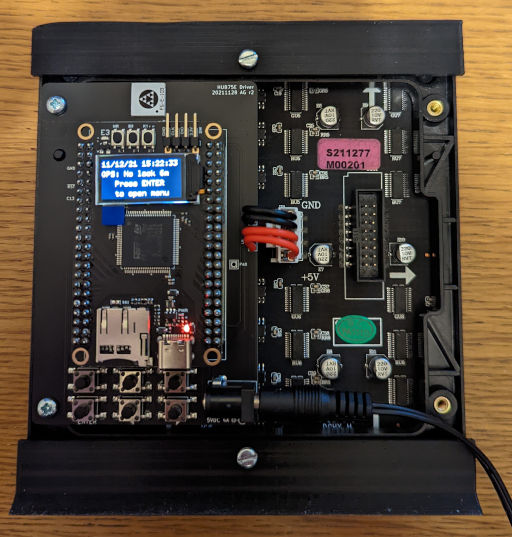
The STM32H743 is on a breakout board from WeAct (thanks, silicon shortage!) and underneath it are the 3v3-to-5v level shifters for the LED, a CR2032 battery for the RTC, and the uBlox GPS reciever. At the top of the PCB is the GPS antenna, and at the bottom are the six user-interface tactile switches.
Power is supplied by a 5V mains adapter, and the breakout board includes a 3v3 SMPS regulator used for the STM32, the LCD, and the uBlox.
Driving the HUB75E
The HUB75E is not trivial to drive from a general purpose microcontroller, as the only control you get is to turn each red/green/blue LED in a single row fully on or off, and then you scan through rows manually. Brightness control is achived by turning LEDs on and off for precise timeslots using binary-coded modulation (BCM). In this implementation, about 200 full frames are drawn each second, and each frame is drawn ten times for the ten BCM phases. A pixel with full brightness is on for just over 70% of the maximum possible time (but given the 1:32 row scanning, this means each pixel is on for at most 2.2% of the frame).
See hub75e.rs for the gory details. The gist is:
- The STM32 stores full framebuffers in DTCM RAM (double-buffered).
- To draw a single frame:
- The two currently active rows of the display are mapped through a 10-bit gamma lookup table and cached in DTCM RAM.
- The row select pins are driven for the currently selected rows.
- For the current BCM phase, the on/off RGB state of each pixel is computed and stored in a byte array in SRAM1.
- The byte array is given to the DMA peripheral to output on the lower byte of one GPIO output data register. The DMA can read from SRAM1 without contending with other CPU activities in DTCM.
- A timer is started which outputs a 15MHz clock signal, and each rising edge also triggers the DMA to write the next byte to the GPIO register.
- On the final DMA byte, the output latch pin is toggled.
- When the DMA completes, the clock timer is stopped and a second timer runs a timed pulse on the output-enable pin, with the pulse length doubling for each BCM phase.
- During the OE pulse, the next phase of BCM pixel data is computed, or if this was the final phase, the next gamma-mapped row is computed.
- After OE pulse, DMA restarts for the next BCM phase.
- After all BCM phases complete, the process repeats for the next row.
QR codes
Just as I started to write my own QR rendering library, I found Nayuki had released a no-std version of their QR code library, so I gratefully vendored that instead, with a few small tweaks to work with the rest of my code. Since all the URLs could be truncated and use only upper-case characters, small efficient QR codes could be generated.
There’s a dedicated button on the back for toggling between the normal display and the QR code, which links to the original blog post for the current day of the route.
JPEGs
I embed 64x64 pixel crops of photographs in the firmware image itself using
Rust’s include_bytes! macro, which is very convenient but does increase
programming times somewhat. About 100kB of JPEGs are embedded (using 4:4:4
chroma sampling and quality 80). The STM32’s JPEG hardware peripheral is used
to decode the JPEGs, and the DMA2D peripheral rearranges the MCUs into a framebuffer.
The JPEGs are shown for the first minute of each hour, or whenever desired by pressing the DISPLAY button to cycle between map/JPEG/off.
Dependencies
This project benefitted greatly from these extremely helpful Rust projects:
- RTIC is a concurrency framework that uses the STM32’s interrupt controller to allow efficiently running multiple tasks and sharing data between them.
- embedded-graphics provides a nice framework for handling graphics and screen displays; in this firmware two displays are run at the same time and embedded-graphics handles font rendering, drawing pixels, and also provides the simulator that enables the desktop version.
- Nayuki’s QR code library made rendering QR codes much easier!